Instructions - how to check the diode with a multimeter (call a tester)
Like most measuring instruments, multimeters (testers) are divided into analog and digital. Their main difference is, that information about the results of measurements of the first kind is transmitted using a certain scale and arrows on it, in the second case, this data is displayed digitally, on the LCD screen.
Analog devices have appeared before, their main advantage is the low price, and the disadvantage is the inaccuracy of measurements. so, if the mark should be as correct as possible, it is recommended to buy a digital multimeter.
All versions of the testers have at least two outputs - red and black.
- The first is used directly for measurements, also sometimes called potential,
- The second is common. Modern models usually also have a switch, thanks to which it is possible to set maximum limits.
How to check a diode with a multimeter?
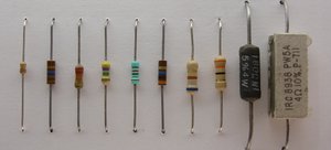
The diode is an element, which conducts electricity in one direction. If you deploy this direction, the diode will be closed. Only if this condition is met, the element is considered operational. Most tester models already have this feature, how to check diode tester.
It is recommended to connect two multimeter probes before starting the test, to make sure it works, and then select "diode test mode". If the tester is analog, this operation is performed using the ohmmeter mode.
Checking diodes with a multimeter does not require additional skills. To make sure the item is working, it is necessary to carry out direct inclusion, so, connect the anode to the positive value (red probe), and the cathode - to minus (black). The breakdown voltage of the diode should appear on the screen or scale of the device, this figure averages from 100 to 800 mV. If you make the reverse inclusion (swap electrodes), the value will be no more than one. From this we can conclude, that the resistance of the device is huge and it does not conduct electricity. If that's exactly what happens, as described above, the electronic element is serviceable and operational.
There are situations, when the diode is connected in both directions when the probes are connected, or does not miss at all (values at direct and return inclusions are equal to one). In the first case, it means, that the diode is pierced, and in the second - he burned out or is in the cliff. Such electronic components are defective and this is easy to check with a tester.
How to check the LED?
When it comes to LEDs, the algorithm of checks is similar, but that fact will further facilitate the task, that when directly turned on, this type of diode will glow. Of course, this will finally make sure, that he is fine.
But it happens, that you need to check zener diodes. Zener diode is one of the types of diodes, its main purpose is to maintain a stable output voltage regardless of changes in current level.
Unfortunately, dedicated function to test this type of electronic components has not yet been implemented in multimeters. However, you can often call them using the same principle, as with diodes. But many experienced radio amateurs claim, that to check the zener diode with a digital tester is very problematic. The reason for this is the fact, that the voltage of the zener diode should be lower, than the voltage at the outputs of the multimeter. It has to do with that, that due to low voltage it is possible to consider the working faulty model, the accuracy of the readings decreases.
If when checking the diode it is necessary to pay attention to the value of the breakdown voltage, in the case of zener diodes, the resistance will be indicative. This figure should be from 300 to 500 Ohm. And similarly to the algorithm of actions with diodes:
- If current is passed in both directions it is called punching,
- If the resistance is too high it is a break.
It is also important to remember, that the digital value when the zener diode rings will be higher than the value of conventional diodes. If you want to distinguish one element from another, such a check will help.
How to check the zener diode
Zener diodes, verification of which did not bring the desired results, inventors are often tested with additional devices, sometimes designing them yourself. One of the easiest ways is to use a voltage-switchable power supply to test. You must first connect a resistor to the anode, which has the value of resistance, optimal for zener diode, and then connect the power supply. Then reconcile the voltage across the diode, rises in parallel on the block. After reaching the stabilization voltage level, this figure should stop growing. In this case, the zener diode is normal, in any difference from the above scheme, it is defective.