The principle of operation of the high pressure fuel pump
In the previous series of articles on the installation of the fuel system of the gasoline engine more than once touched upon the topic of high-pressure fuel pump for diesel engines and gasoline engines with direct (direct) fuel injection.
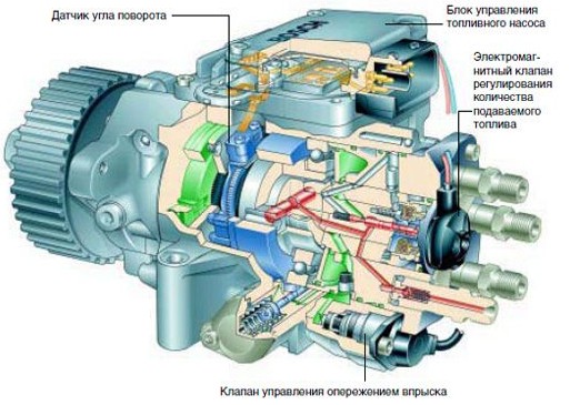
This article is a separate material, which describes the design of a high pressure diesel fuel pump, its purpose, potential malfunctions, scheme and principles of work on the example of the device of such a fuel supply system for this type of internal combustion engine. so, let's get down to business.
What is a fuel pump?
High pressure fuel pump is abbreviated as a fuel pump. This device is one of the most complex in the design of a diesel engine. The main task of such a pump is the supply of diesel fuel under high pressure.
The pumps supply fuel to the cylinders of the diesel engine under a certain pressure, as well as strictly at a certain point. Portions of the supplied fuel are measured very accurately and correspond to the degree of load on the engine. Pumps are distinguished by the method of injection. There are pumps of direct action , as well as pumps with battery injection.
Direct-acting fuel pumps have a mechanical plunger drive. The processes of fuel supply and injection take place at the same time. In each separate cylinder of the diesel internal combustion engine a certain section of the pump delivers the necessary dose of fuel. Pressure, which is necessary for effective spraying, is created by the movement of the plunger of the fuel pump.
TNVD with cordless injection differs in that, that the drive of the working plunger is affected by the compressive forces of the compressed gases in the cylinder of the engine or the impact is detected by springs. There are fuel pumps with hydraulic accumulators, which have found application in powerful low-speed diesel internal combustion engines.
It is worth noting, that systems with the accumulator are characterized by separate processes of injection and injection. Fuel under high pressure is pumped by a fuel pump into the battery, and only then comes to the fuel injectors. This approach provides efficient spraying and optimal mixing, which is suitable for the entire range of loads on the diesel unit. The disadvantages of this system include the complexity of the design, which was the reason for the unpopularity of such a pump.
Modern diesel plants use technology, which is based on control of solenoid valves of nozzles from the electronic control unit with the microprocessor. This technology is called "Common Rail".
The main causes of malfunctions
TNVD is an expensive device, which is very demanding on the quality of fuels and lubricants. If the car is operated on low quality fuel, such fuel must contain solid particles, drank, water molecules, etc.. d. All this leads to the failure of plunger pairs, which are installed in the pump with the minimum tolerance, measured in microns.
Low-quality fuel easily disables the injectors, which are responsible for the process of spraying and injecting fuel.
Common signs of malfunctions in the pump and injectors are the following deviations from the norm:
- fuel consumption is significantly increased;
- there is increased smoky exhaust;
- in the process of work there are extraneous sounds and noise;
- power and recoil from the engine are noticeably falling;
- there is a difficult start;
Modern engines with fuel pumps are equipped with an electronic fuel injection system. The ECU dispenses the fuel supply to the cylinders, distributes this process over time, determines the required amount of diesel fuel. If the owner notices the slightest malfunction of the engine, then this is an immediate reason to contact the service immediately. The power plant and fuel system are thoroughly inspected using professional diagnostic equipment. During the diagnosis, experts determine numerous indicators, among which are paramount:
- the degree of uniformity of fuel supply;
- pressure and its stability;
- shaft speed;
The evolution of the device
The stringency of environmental regulations and requirements for emissions of harmful substances into the atmosphere has led to this, that mechanical high-pressure fuel pumps for diesel cars began to be replaced by electronically controlled systems. The mechanical pump simply could not provide the fuel metering with the required high accuracy, and was unable to respond as quickly as possible to dynamically changing engine modes.
World-renowned manufacturers Bosch, Nippon Denso and others have proposed electronic fuel management systems. These developments were based on the fuel pump VE. Such systems allowed to increase the accuracy of fuel dosing in each cylinder separately.
The introduction of electronic systems provided a reduction between the cycles of instability of the combustion process of the fuel-air mixture, as well as reducing irregularities in the process of idling the diesel engine.
Some systems had a quick-acting valve in their design, which allowed to divide the process of fuel injection into two phases. Two-phase injection led to a final reduction in the rigidity of the combustion process of the mixture.
The obtained accuracy in the process of controlling the injection system provided a reduction in emissions of toxic substances due to more complete combustion of the fuel-air mixture, and the increasing efficiency of such combustion increased the efficiency of the engine and increased the final power of the power plant.
Electronic systems received fuel pumps of the distributive type. Such pumps are equipped with controlled devices, which adjust the position of the dispenser. Additionally, there is a valve to anticipate fuel injection.
The principle of operation of the system
The ECU receives the appropriate signals from various sensors. The position of the accelerator pedal is taken into account, engine shaft speed, coolant temperature and fuel temperature. The electronic control unit receives data on the lifting of the injector needle, vehicle speed, air boost pressure and its inlet temperature.
The ECU processes the information received from the sensors, and then sends a signal to the pump. This ensures the supply of the required and optimal amount of fuel to the injectors. Additionally, the best injection advance angle is provided, taking into account the specific operating conditions of the engine. Any additional load is immediately noted by the ECU, a signal arrives at the pump and there is an increase in fuel supply to compensate for the increased loads.
The electronic control unit monitors the operation of the glow plugs. The ECU monitors the incandescence period, the mode of operation of glow plugs and the period after glowing. All this takes into account the dependence on temperature.
The following is a diagram of the electronic control of a Bosch VE single-piston pump for a diesel engine:
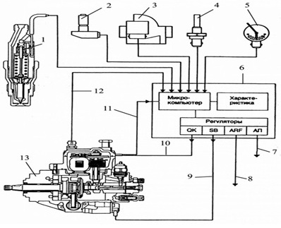
- injection start sensor;
- crankshaft speed sensor and TDC;
- air flow meter;
- OS temperature sensor;
- accelerator pedal position sensor;
- control unit;
- the device of the accelerator of start-up and warming up of the internal combustion engine;
- device for controlling the exhaust gas recirculation valve;
- device for controlling the angle of advance of fuel injection;
- device for controlling the drive of the dosing clutch;
- dispenser stroke sensor;
- fuel temperature sensor;
- high pressure fuel pump;
A key element in this system is the device for moving the dosing coupling PNVT (10). The control unit controls the fuel supply processes (6). The information comes to the unit from the sensors:
- injection start sensor , which is installed in one of the nozzles (1);
- TDC sensor and crankshaft speed (2);
- air flow meter (3);
- coolant temperature sensor (4);
- accelerator pedal position sensor (5);
The set optimal characteristics are stored in the memory of the control unit. Based on information from sensors, The ECU sends signals to the control mechanisms of cyclic supply and the angle of advance of the injection. This is how the value of the cyclic fuel supply is regulated in different modes of operation of the power unit, as well as at the time of cold start of the engine.
Actuators have a potentiometer, which sends a feedback signal to the ECU, due to which the exact position of the dosing coupling is determined. The advance of the fuel injection advance is regulated by a similar principle.
The ECU is responsible for generating signals, which provide regulation of numerous processes. The control unit stabilizes the idle speed, regulates recirculation of the fulfilled gases with definition of indicators on signals of the sensor of a mass expense of air. The unit compares real-time signals from sensors with those values, which are programmed in the form of optimal. Next is the transmission of the output signal from the ECU to the servomechanism, which provides the required position of the dosing clutch. At the same time high accuracy of adjustment is reached.
This system has a self-diagnostic program. This allows you to test emergency modes to ensure the movement of the vehicle, even in the presence of a number of certain faults. Complete failure occurs only when the ECU microprocessor breaks down.
The most common cyclic feed control solution for a single-pressure high-pressure distribution pump is the use of an electromagnet (6). This magnet has a rotating core, the end of which is connected by means of an eccentric to the dosing coupling (5). Electric current passes in the winding of the electromagnet, the angle of rotation of the core may be from 0 up to 60 °. This is how the dosing clutch moves (5). This coupling as a result regulates cyclic supply of the pump.
Single-plunger pump with electronic control
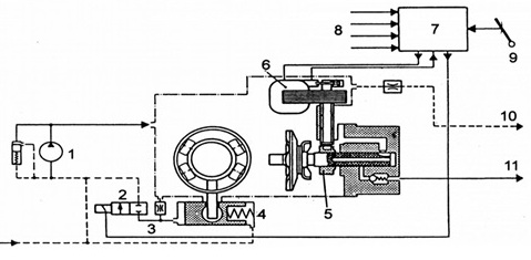
- PNVT;
- solenoid valve to control the automatic fuel injection advance;
- cracks;
- the cylinder of the automatic machine of advance of injection;
- dispenser;
- electromagnetic device for changing the fuel supply;
- ECU;
- temperature sensor, boost pressure, position of the fuel supply regulator;
- control lever;
- fuel return;
- fuel supply to the injector;
The injection advance machine is controlled by a solenoid valve (2). This valve regulates the fuel pressure, which acts on the piston of the machine. The valve is characterized by operation in pulse mode on the principle of "opening - closing". This allows you to modulate the pressure, depending on the speed of the internal combustion engine shaft. At the time of opening the valve, the pressure drops, and this entails a reduction in the angle of advance of the injection. The closed valve provides an increase in pressure, which moves the piston of the machine to the side, when the injection advance angle is increased.
These EMC pulses are determined by the ECU and depend on the operating mode and temperature of the engine. The moment of the beginning of injection is defined by means of that, that one of the nozzles is equipped with an induction needle lift sensor.
Executive mechanisms, which affect the control elements of fuel supply in the pumping station of the distribution type, are proportional to the electromagnetic, linear, torque or stepper motors, which act as a drive for the fuel dispenser in these pumps.
Nozzle with needle lift sensor
The electromagnetic actuator of the distributive type consists of the sensor of the course of the batcher, the executing device itself, dispenser, the valve of change of an angle of the beginning of injection, which is equipped with an electromagnetic drive. The nozzle has a built-in excitation coil in its housing (2). The ECU supplies there a certain reference voltage. This is done to keep the current in the electrical system constant and independent of temperature fluctuations.
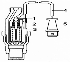
Nozzle, equipped with a needle lift sensor, consists of:
- adjusting screw (1);
- excitation coils (2);
- stock (3);
- wiring (4);
- electrical connector (4);
This current results in the creation of a magnetic field around the coil. At the time of lifting the needle nozzle core (3) carries out change of a magnetic field. This causes a change in voltage and signal. When the needle is in the process of lifting, then the pulse reaches its peak and is determined by the ECU, which controls the angle of advance of the injection.
The electronic control unit compares the received pulse with the data in its memory, which correspond to different modes and operating conditions of the diesel unit. The ECU then sends a return signal to the solenoid valve. The specified valve is connected to the working chamber of the injection advance machine. Pressure, affecting the piston of the machine, begins to change. The result is the movement of the piston under the action of a spring. This changes the angle of advance of the injection.
The maximum pressure, which is achieved by means of electronic control of fuel supply on the basis of the fuel pump VE, is an indicator to 150 kgf / cm2. It is worth noting, that this scheme is complex and outdated, voltages in the cam drive have no further prospects. The next stage in the development of pumping stations is a new generation of schemes.
The VP-44 pump and the system of direct injection of the diesel internal combustion engine
This scheme is successfully used on the latest models of diesel cars from the world's leading concerns. These include BMW, Opel, Audi, Ford, etc.. d. Pumps of this type allow to receive an indicator of injection pressure on a mark 1000 kgf / cm2.
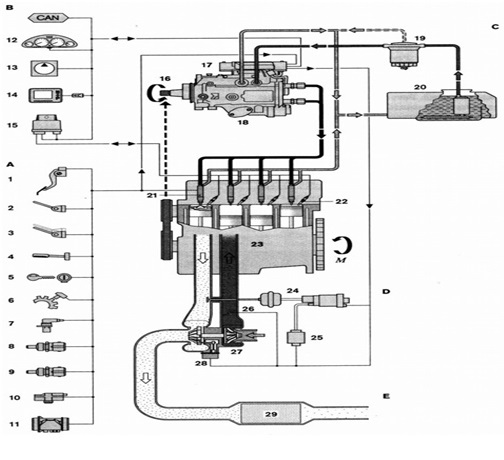
Direct injection system with fuel pump VP-44, shown in the figure, includes:
- A-group of actuators and sensors;
- B-group of devices;
- C-low pressure circuit;
- D - system for air supply;
- E - system for removal of harmful substances from exhaust gases;
- M-torque;
- CAN on-board communication bus;
- fuel control pedal travel sensor;
- clutch release mechanism;
- contact of brake pads;
- vehicle speed regulator;
- glow plug and starter switch;
- vehicle speed sensor;
- inductive crankshaft speed sensor;
- coolant temperature sensor;
- air temperature sensor, entering the intake;
- boost pressure sensor;
- film-type sensor for measuring the mass flow of air at the inlet;
- combined instrument panel;
- electronically controlled air conditioning system;
- diagnostic connector for scanner connection;
- switch-on time control unit for glow plugs;
- PNVT drive;
- ECU for engine management and PNVT;
- PNVT;
- filtering fuel cell;
- fuel tank;
- injector sensor, controls the movement of the needle in the 1st cylinder;
- pin candle;
- propulsion;
This system has a characteristic feature, which consists of a combined control unit PNVT and other systems. The control unit structurally has two parts, end stages and power supply of electromagnets, located on the fuel pump housing.
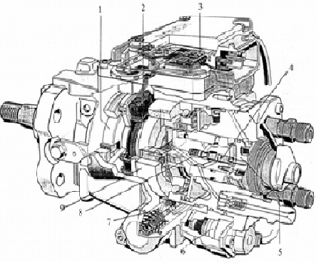
Device TNVD VP - 44
- fuel pump;
- pump shaft position and frequency sensor;
- control unit;
- valve;
- electromagnet feed;
- electromagnet of the advance advance angle;
- hydraulic actuator to change the angle of advance of the injection;
- rotor;
- cam washer;
The system includes a low pressure circuit. The fuel pump in the VP-44 pump is a gate pump. There is a dependence of pressure, which is created by the fuel pump on the fuel injection side of that frequency, with which the rotation of the pump wheel. The specified pressure at increase in speed of rotation has a disproportionate indicator.
The pressure regulating valve is located close to the fuel pump. It is connected to the outlet groove through a special hole for flow. The valve is responsible for changing the injection pressure of the fuel injection pump depending on the required fuel consumption. Fuel, which injects the fuel pump, enters the PNVT and its pumping section, thus entering the injection advance device.
Hydraulic scheme of the pump:
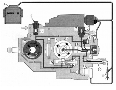
control unit;
- pressure regulating valve;
- pressure control valve piston;
- bypass throttle valve;
- offtake;
- throttle;
- high pressure fuel pump control unit;
- piston damper;
- fuel solenoid control solenoid valve;
- discharge valve;
- nozzle;
- solenoid valve of the injection start unit;
- distribution rotor;
- pump section of the pump with plungers, moving radially;
- PNVT drive shaft rotation angle sensor;
- injection advance device;
- fuel pump;
Low pressure circuit
If the fuel pressure exceeds the specified value, then using the end edge of the piston (3) the holes open. These holes are located radially. Through them, the fuel flow flows through the channels of the pump to a special supply groove. In those cases, when the pressure is low, then the radial holes are closed, as they are affected by the force of the spring. The tension of the spring determines the amount of pressure.
Cooling fuel pump, as well as the removal of air is carried out by passing fuel through the bypass throttle valve (4), which is screwed to the pump housing.
With the help of this valve the fuel is diverted through the bypass channel (5). The valve has a spring-loaded ball in its housing. This design allows fuel to flow only then, when a certain pressure is reached in the channel itself.
Throttle (6) has a small diameter. Such a choke is connected to the discharge line, which is located in the valve body and runs parallel to the main channel for fuel removal. The specified throttle is responsible for automatic removal of air from the fuel pump. The device of a contour of a low pressure of TNVD is calculated on that, that through the throttle valve bypass in the fuel tank always returns a certain amount of fuel.
High pressure circuit
The high pressure circuit is considered to be the pump itself, as well as a device for distributing and adjusting the amount and timing of the feed. Only one element is used for this, which is called a high pressure solenoid valve.
These systems are responsible for creating a high pressure pump section of the pump with radial movement of the plungers. This section creates such pressure, what is needed to inject fuel at a pressure of about 1000 kgf / cm2. It is actuated by a drive shaft, and the design consists of:
- connecting washer;
- shoes with rollers;
- cam washer;
- injection plunger front (heads) camshaft;
The figure below shows an example of the location of the plungers:
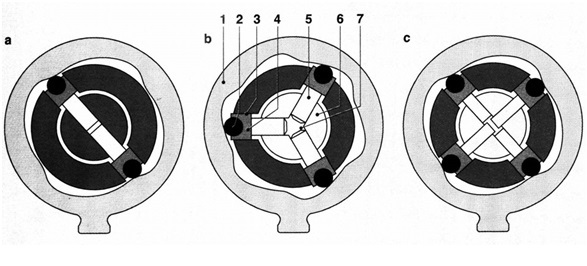
- a-cylinder four or six;
- b-for six cylinders;
- c-for four cylinders;
- cam washer;
- video clip;
- guide grooves of the drive shaft;
- roller shoe;
- injection plunger;
- camshaft;
- high pressure chamber;
The system works this way, that the torque from the drive shaft is transmitted through the coupling washer and the splined connection. This moment goes to the camshaft. Guide grooves (3) perform this function, to through shoes (4) and there are videos in them (2) to use in work pump plungers (5) So, that it corresponds to that internal profile, which has a cam washer (1). The number of cylinders in the diesel engine is equal to the number of cams on the washer.
The injection plungers in the housing of the camshaft are located radially. For this reason, such a system is called a pump. Plungers carry out joint extrusion of the arrived fuel on an ascending profile of a cam. Then the fuel enters the main high pressure chamber (7). There may be two in the pump, three or more pump plunger, depending on the planned loads on the engine and the number of cylinders (a, b, c).
The process of fuel distribution using the distributor housing
At the heart of this device are:
- flange (6);
- distribution sleeve (3);
- the rear part of the camshaft is located in the camshaft (2);
- closing needle (4) high pressure solenoid valve (7);
- accumulating membrane (10), which separates the cavity, responsible for pumping and draining;
- high-pressure line fittings (16);
- discharge valve (15);
In the figure we see the distributor housing itself:
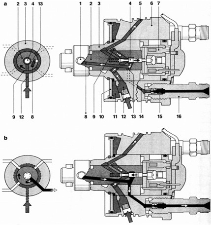
- and - the phase of refueling;
- b-phase of fuel injection;
This system consists of:
- plunger;
- camshaft;
- distribution sleeve;
- closing needle of the high pressure solenoid valve;
- channel for refueling;
- flange;
- high pressure solenoid valve;
- high pressure chamber channel;
- annular fuel inlet channel;
- accumulating membrane for the separation of pumping cavities and drain cavity;
- cavity behind the membrane;
- low pressure chambers;
- distribution groove;
- exhaust channel;
- discharge valve;
- high-pressure line fitting;
At the stage of filling the down profile of the cams plungers (1), moving radially, move outwards and move to the surface of the cam washer. Closing needle (4) at this point is in a free state and opens the fuel inlet. The fuel passes through a low pressure chamber (12), ring channel (9) and a needle. Next, the fuel is directed from the fuel pump channel (8) camshaft and enters the high pressure chamber. All excess fuel flows back through the return channel (5).
Injection is carried out by means of plungers (1) and needles (4), which is closed. Plungers begin to move on the ascending profile of cams to an axis of a camshaft. This increases the pressure in the high pressure chamber.
Fuel, already under high pressure, is directed through the channel of the high pressure chamber (8). It passes through the distribution groove (13), which in this phase connects the camshaft (2) with exhaust channel (14), Union (16) with discharge valve (15) and a high-pressure line with a nozzle. The last stage is the entry of diesel fuel into the combustion chamber of the power plant.
How is fuel dosing. High pressure solenoid valve
Solenoid valve (valve for setting the moment of injection) consists of such elements:
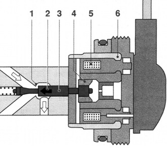
- valve seat;
- the direction of closing the valve;
- needle valve;
- anchor electromagnet;
- coil;
- electromagnet;
The specified solenoid valve is responsible for cyclic supply and dosing of fuel. This high pressure valve is built into the high pressure circuit of the pump. At the very beginning of the injection on the coil of the electromagnet (5) the signal voltage of the control unit is supplied. Anchor (4) moves the needle (3) by pressing the latter to the saddle (1).
When the needle is pressed tightly to the saddle, then the fuel does not come. The fuel pressure in the circuit increases rapidly for this reason. This allows you to open the corresponding nozzle. When the right amount of fuel was found in the combustion chamber of the engine, then the voltage on the coil of the electromagnet (5) disappears. The high pressure solenoid valve is opened, which entails a decrease in pressure in the circuit. Reducing the pressure causes the fuel injector to close and the injection to stop.
All that accuracy, with which this process is carried out, directly depends on the solenoid valve. If you try to explain in more detail, then from the end of the valve. This moment is solely determined by the absence or presence of voltage on the solenoid valve coil.
Excess fuel is injected, which continues to be pumped until the plunger roller passes the upper point of the cam profile, carry out movement on the special channel. The end of the path for the fuel is the space behind the accumulating membrane. High pressure jumps occur in the low pressure circuit, which are damped by the accumulating membrane. Additional is that, that this space saves (accumulates) accumulated fuel for filling before the next injection.
The engine is stopped by means of the solenoid valve. The point is, that the valve completely blocks the injection of fuel under high pressure. This solution completely eliminates the need for an additional stop valve, which is used in distribution pumps, where the control edge is controlled.
The process of attenuation of pressure waves by means of a discharge valve with backflow choking
This discharge valve (15) with throttling of a return stream after completion of injection and a fuel portion interferes with the subsequent opening of a spray nozzle. This completely eliminates this phenomenon, as an additional injection, which is the result of pressure waves or their derivatives. This additional injection increases the toxicity of exhaust gases and is an extremely undesirable adverse event..
When the fuel supply starts, then the cone of the valve (3) opens the valve. At this point, the fuel is already being pumped through the fitting, penetrates the high pressure line and goes to the nozzle. The end of fuel injection causes a sharp drop in pressure. For this reason, the return spring forcibly presses the valve cone against the valve seat. When closing the nozzle there are back pressure waves. These waves are successfully extinguished by the throttle valve. All these actions prevent unwanted fuel injection into the working combustion chamber of the diesel engine..
Injection advance device
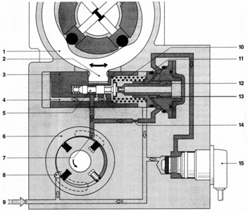
This device consists of the following elements:
- cam washer;
- ball pin;
- plunger for setting the injection advance angle;
- inlet and outlet channel;
- control valve;
- gate pump for fuel injection;
- fuel drainage;
- fuel inlet;
- supply from the fuel tank;
- control piston spring;
- reversible spring;
- control piston;
- annular chamber of a hydroresistance;
- throttle;
- solenoid valve (closed) setting the moment of injection;
The optimal combustion process and the best power characteristics of the diesel engine are possible only then, when the moment of the beginning of combustion of mix occurs in the certain position of a cranked or piston in the cylinder of the diesel engine.
The injection advance device performs one very important task, which is, to increase the angle of the fuel supply at that moment, when there is an increase in crankshaft speed. This device constructively includes:
- PNVT drive shaft rotation angle sensor;
- control unit;
- solenoid valve setting the moment of injection;
The device provides the same optimal moment of the beginning of injection, which is ideal for engine operation and load. There is a compensation for the temporary shift, which is determined by the reduction of the period of injection and inflammation with increasing speed.
This device is equipped with a hydraulic drive and is built into the lower part of the pump housing in this way, to be located across the longitudinal axis of the pump.
Operation of the injection advance device
Kulachkov washer (1) enters with a ball pin (2) transverse hole of the plunger (3) so, that the translational movement of the plunger is transformed into a rotation of the cam washer. The plunger in the center has a control valve (5). This valve opens and closes the control holes in the plunger. Along the axis of the plunger (3) there is a control piston (12), which is loaded by a spring (10). The piston is responsible for the position of the control valve.
Solenoid valve to set the moment of injection (15) is across the axis of the plunger. Electronic unit, operating the pump, influences the plunger of the injection advance device by means of this valve. The control unit supplies current pulses in continuous mode. Such pulses are characterized by a constant frequency and variable duty cycle. The valve changes the pressure, which affects the control piston in the design of the device.
Let's summarize
This material is aimed at the most accessible and understandable acquaintance of users of our resource with a complex device of a high-pressure fuel pump and an overview of its main elements.. The device and the general principle of work of TNVD allow to speak about faultless operation only on condition of refueling of the diesel unit with qualitative fuel and motor oil.
As you have already understood, low-grade diesel is the main enemy of complex and expensive diesel fuel equipment, repair of which is often not very cheap.
If you operate the diesel carefully, strictly adhere to and even reduce the service intervals for lubricant replacement, take into account other important requirements and recommendations, then the pump will certainly respond to its caring owner with exceptional reliability, economy and enviable durability.