Designation and form of representation of welds in the drawings: types of designations, features of the presentation
Basic notation
Products prepared for welding are often made of materials, which differ not only in thickness, but also in size and shape. Also, the connecting parts may differ in their location relative to each other. Various weld designations may be provided in the drawings, which is determined primarily by the relative position of the welded structural elements. Current state standards define the following main types of connections:
- "C" docking;
- "C" end;
- "U" angular;
- "N" overlapping;
- "T" Brands.
docking
Often in the drawings you can find the designation of the butt weld, which means the connection of products, located within one surface or plane. Adjacent end points are the points of contact when joining parts by welding.
butt
Under the end means a combination of elements by welding on the end sides of the products, where the side parts are located together. This method is used in those situations, when it is necessary to combine elements of thin metal to prevent burns. A very important point is that, that in the drawings, in addition to the direct designation of a weld, there must be an explanation, that reveals the essence of it, what type of weld is meant. Such additional information should be present in those cases, when identical letters are used to denote welds.
Overlapping
When performing overlapping welds, the capital letter "H" is usually used in the drawings., which serves as an explanation for the created seam. The peculiarity of such connections is that, that the elements are parallel to each other, and one of them must partially overlap the other.
Brands
If the drawings provide a T-shaped weld, then the letter "T" is used as an explanatory symbol. There is a connection for this, that one product is welded by the end part of another product in the same place at an angle, which can reach 90 degrees.
angles
The capital letter "B" is used to indicate the angular weld in the drawings. Such joints are characterized by direct welding of products, acute or obtuse angle relative to each other.
Often one of the two marks can be used in the drawings to indicate the weld:
- visible;
- invisible.
And this rule applies in any case, regardless of the type of welding method used.
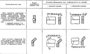
If the drawing shows the visible type of seam, then as a label it will correspond to a solid line. In the case of the invisible type, the dotted line is usually a hint. To indicate in the drawings a single weld point, belonging to the category of visible ??notes, mathematical sign "+" is used. As for the invisible point, then no designations are provided for it.
Features of the indication of seams on the drawing
In some situations, the drawing may involve seams, created according to the same standards. Identical designations will then be used for such projects, moreover, such information must be given in the technical requirements of this drawing.
Sometimes as a way to explain the labels for the seams, which in the drawings correspond to each other, a certain number can be used. However, this rule applies only if, that there is an absolute similarity between them, and the image used is one-sided, let's say, they are presented only on the front or back. The situation is permissible, when the seams do not have any markings. For such cases, the drawing must include a mark, performed in the form of a line, which is presented ??like a callout without sticks.
If the drawing shows symmetrical products, then uses footnote lines to indicate the weld. And as a mark for seams it is admissible to use only one of symmetrical parties of a product. This option is allowed only in the presence of an axis of symmetry.
Drawing: requirements of GOST
If the drawing, made in accordance with GOST, contains elements, relating to one product, connected by seams of the same type, then it is allowed to use footnote lines for their marks. And the important point is that, that only one specific part of the part may provide for the marking of the seam. Best, if it is done in the form of an image, and next to it is a footnote line.
Possible situations, when there are no marks in the drawing for individual welds defined by the current standard in the form of footnote lines. Such a decision is dictated by them, that the necessary information is contained in the technical requirements and notes to the drawing, where they are presented in the form of welded joints. That the drawing meets the requirements of GOST, it must be marked with welds. The necessary information must be reflected in the technical requirements, the information provided there should give an idea of the type of weld, the sizes of details and features of their design, the location of welded joints within the cross section.
There is a single set of requirements, which must satisfy all seams or groups of welds, which are shown in the drawing. And this information must be provided in a special form:
- table;
- technical description.
Welding also has its own peculiarities of representation in the drawing. It should be given in that form, which is enshrined in current requirements. Only on condition, that the drawing was designed with all the requirements in mind, you can count on it, that the welder will not have problems during operation, and he will be able to solve the problem with minimal time and without errors. In that case, if mistakes were made in compiling the drawing, which violate the requirements of the current state standard, then it will not be approved by the authorities at first.
conclusion
Proper assembly of drawings for welding is no less important step, than the work of joining metal products. There are certain requirements for weld designations, which must be observed regardless of the type of welding used. The notation used for welds provides not only clarity of the drawing, but also simplify the work for the welder. Each name has its own characteristics, therefore, errors at this stage can be costly, as the welder will be guided by the reflected marks in the drawing, performing the task set before him.
The fundamental document, which establishes the requirements for the submission of markings for welded joints, is a state standard. So not just people, who develop drawings, but also those, for whom it will serve as a basis in the process of work, must be sufficiently aware of all requirements and the accompanying notes. This knowledge helps to avoid mistakes and misunderstandings, which allows you to count on the accurate implementation of the project with the use of structures, requiring the creation of welded joints.